


Common Pipe Grades Used in Industrial Applications
Summary: Choosing the right pipe for an industrial application isn’t just about picking a size, it’s about understanding how dimensions, schedules, wall thickness, and grades all work...

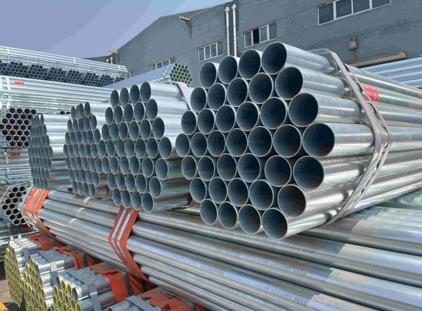
In industrial piping, selecting the wrong grade or misreading dimensional data can create problems that show up well into a project during fabrication, installation, or even after the system is in service. The pipe chart size exists to prevent exactly that. It’s a structured reference that brings together pipe dimensions, wall thicknesses, weights, and schedule information in one place.
But a chart is only useful if you understand what’s behind it. This post looks at the common pipe grades found in industrial applications and how the pipe size chart reflects the dimensional differences between them.
What a Pipe Chart Size Actually Tells You
A steel pipe size chart is a reference table where each row represents a pipe size, and each column represents a schedule. For every combination of size and schedule, the chart typically shows two values: the wall thickness and the weight per foot.
That’s the core of it. Once you understand those two data points and how they change across sizes and schedules, reading any pipe chart becomes straightforward.
The Three Key Dimensions: OD, Wall Thickness, and Weight
Outer Diameter (OD) stays fixed: This is one of the most commonly misunderstood points in pipe sizing. The OD does not change with the schedule. A 2-inch pipe always has an OD of 2.375 inches. A 6-inch pipe always has an OD of 6.625 inches, regardless of what schedule it is. Nominal pipe size is a label, not a direct measurement.
Wall thickness is what changes: When you move from Schedule 40 to Schedule 80, the outer diameter stays the same, but the wall gets thicker. For a 2-inch pipe, Schedule 40 carries a wall thickness of 0.154 inches, while Schedule 80 carries a wall thickness of 0.218 inches. That thicker wall means more material, a higher pressure rating, and less internal space.
Weight follows thickness: As wall thickness increases, so does weight per foot. For that same 2-inch pipe, Schedule 40 weighs 3.66 lbs per foot while Schedule 80 comes in at 5.03 lbs per foot. This matters practically, as weight affects transportation, handling, and structural support requirements on any project.
How Pipe Schedules Work
Schedules are a standardized way to define wall thickness across pipe sizes. The most commonly used schedules in industrial applications are:
- Schedule 5 and 10 — lighter walls, used where pressure demands are lower and weight reduction matters.
- Schedule 40 — the standard for most general service applications. It’s the most widely referenced schedule in a pipe chart size.
- Schedule 80 — heavier wall, used where higher pressure ratings or additional mechanical strength are required.
- XXH (Double Extra Heavy) — for the most demanding high-pressure or high-stress applications.
To put the difference in perspective: a 4-inch pipe at Schedule 40 has a wall thickness of 0.237 inches, while the same pipe at Schedule 80 is 0.337 inches. That difference may look small on paper, but in terms of pressure capacity, it’s significant for pipe grades.
A Reference: Pipe Size Chart Extract
Here’s a sample extract showing how dimensions, schedules, and weight relate across common sizes:
|
Pipe Size |
OD (inches) |
Schedule |
Wall Thickness (inches) |
Weight (lbs/ft) |
|
2″ |
2.375 |
SCH 40 |
0.154 |
3.66 |
|
2″ |
2.375 |
SCH 80 |
0.218 |
5.03 |
|
4″ |
4.500 |
SCH 40 |
0.237 |
10.80 |
|
4″ |
4.500 |
SCH 80 |
0.337 |
15.00 |
|
6″ |
6.625 |
SCH 40 |
0.280 |
18.99 |
|
6″ |
6.625 |
SCH 80 |
0.432 |
28.60 |
Reading the chart is simple: start with the pipe size, move across to the schedule, and read the wall thickness and weight per foot. Once you’ve done it a few times, it becomes second nature.
Common Pipe Grades and Where They Appear in the Chart
The pipe chart size aligns with widely used industry standards. In industrial applications, you’ll commonly encounter pipes specified under ASTM and API standards, with grades that reflect different strength levels and application requirements.
ASTM Standards cover a broad range of pipe grades used across water, structural, and process applications. These grades appear in the pipe chart alongside scheduled dimensions and are used in ERW, seamless, and welded pipe.
API 5L Grades are the standard for oil and gas line pipe. The API 5L grade range runs from Grade B at the lower end up through X42, X52, X60, X65, X70, and into higher-strength grades up to X120 for the most demanding pipeline applications. As the grade number increases, so does the minimum yield strength, which often influences the wall thickness selected for a given pressure requirement.
In practical terms, when you’re looking at a pipe chart size for an API 5L pipeline project, you’re using the dimensional data to confirm that the selected size and schedule will meet both the physical and performance requirements of the design.
Pipe Types Covered: The pipe size chart reflects different manufacturing types: seamless, ERW (Electric Resistance Welded), and DSAW (Double Submerged Arc Welded). Each type is available in specific size ranges and grade combinations, and the chart helps cross-reference which dimensions apply to each.
Non-Scheduled Sizes: Where the Chart Gets More Flexible
Not every pipe in industrial use falls neatly into standard schedules. Non-scheduled sizes are common in pipeline and oil and gas work. These are typically listed with specific OD values such as 6 5/8″, 8 5/8″, or 10 3/4″ alongside defined wall thickness options and their corresponding weights rather than a schedule designation.
These sizes appear frequently in real project requirements, particularly for gathering systems, transmission lines, and structural applications. A pipe chart size that includes non-scheduled dimensions alongside standard schedules is more useful in practice because it reflects what’s actually used in the field.
How to Calculate Pipe Weight Manually
The pipe chart size also supports manual weight verification. The formula is:
|
(OD − Wall Thickness) × Wall Thickness × 10.69 |
This gives weight per foot in pounds. It’s useful when double-checking chart values, working with custom wall thickness specifications, or verifying numbers for non-standard sizes that may not appear in every reference table.
How to Read a Pipe Chart Size Without Overthinking It
The most practical approach to any pipe chart is to keep it simple:
Start with the pipe size you’re working with. Move across to the schedule or wall thickness that matches your project requirement. Read the two numbers — wall thickness and weight per foot. That’s enough information to confirm selection, verify specifications, or compare options side by side.
The chart is a reference tool, not a design document. It helps answer three questions quickly: how thick is this pipe, how much does it weigh, and does it fit the application? For detailed engineering or project-specific pressure calculations, the chart provides the dimensional input but shouldn’t replace full design review.
Why the Pipe Chart Size Matters for Grade Selection
Grade and dimensions are connected. A higher-strength grade may allow for a thinner wall to meet the same pressure requirement, while a lower grade may require a heavier schedule to compensate. Without accurate dimensional data from a pipe chart, it’s difficult to make that comparison reliably.
This is especially true when working across a range of sizes on the same project. A pipeline that changes diameter along its route, which is common in gathering and distribution systems, requires a consistent dimensional reference to ensure that grade, schedule, and size selections remain compatible from one segment to the next.
Spec It Right the First Time
The difference between a smooth project and a costly one often comes down to whether the pipe matches the spec from the start. B&W Pipe, Inc. stocks carbon steel pipe across grades, schedules, and sizes, seamless, ERW, and DSAW, so what you order is exactly what your project requires.
Call (281) 391-6688 or email sales@bwpipe.biz to talk to our team.
Frequently Asked Questions (FAQs)
Q1: What does a pipe schedule indicate?
It indicates wall thickness, not pipe diameter. A higher schedule means a thicker wall on the same nominal pipe size.
Q2: Does changing the schedule change the outer diameter?
No. The OD stays fixed for a given nominal pipe size. Only the wall thickness and, therefore, the internal diameter and weight change with schedule.
Q3: Why does pipe weight matter in project planning?
Because it affects transportation costs, installation handling, and structural support requirements. Heavier pipe needs more robust support systems and adds to overall project logistics.
Q4: What is the difference between ASTM and API 5L pipe grades?
ASTM grades cover a broad range of pipe types including structural, water, and process service. API 5L grades are specifically for line pipe used in oil and gas applications, with grades defined by minimum yield strength from Grade B through X120.
Q5: What are non-scheduled pipe sizes?
These are pipes listed by specific OD and wall thickness rather than a schedule designation. They’re common in pipeline and oil and gas work and often appear alongside standard scheduled sizes in a complete pipe chart size reference.
Q6: Can I use the pipe size chart to calculate weight manually?
Yes. The formula is: (OD − Wall Thickness) × Wall Thickness × 10.69. This gives weight per foot and is useful for verifying chart values or working with custom dimensions.






No Comment! Be the first one.